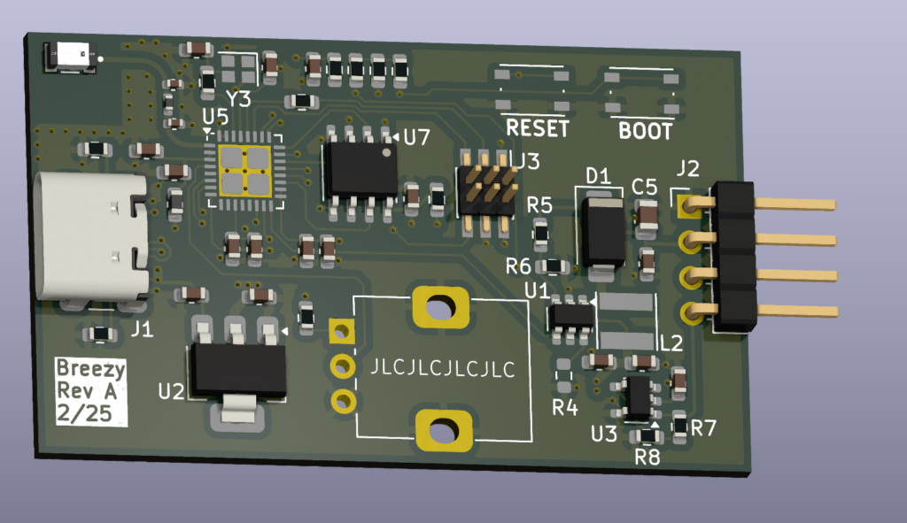
Goal: Control a 12V PWM PC fan via a rotary pot or WiFi connection.
For a speedup and reference, I used the Intel 4-Wire Pulse Width Modulation (PWM) Controlled Fan Rev1.3 specification and the Noctua NF-F12 data sheet.
Some high level requirements I identified are as follows:
- Power input USB type C USB 2.0
- Power output 4 pin 0.1″ pitch right angle male header
- PWM output 5V push/pull at 25kHz
- Tachometer input with 3.3V pullup
- 10k rotary potentiometer
- ESP32-C3 microcontroller
Since it will be taking in 5V but needs to provide 12V, a boost converter is needed. The TI TLV61048 was selected because of its simplicity and low cost. An inductor and diode that are already in my parts inventory will work with this chip to generate a reasonable 12V power rail. The chip claims a +-2.5% accuracy and the Intel spec requires +-5%. The final tolerance will be close but probably OK for this one off project.
For the control signal, Intel requires a 5V 25kHz +-4kHz signal and recommend a push pull type circuit. The ESP-C3 is a 3.3V device. 25kHz isn’t all that fast. Looking through my parts again, I have a tiny single op-amp. Using this with a supply of 5V and a gain of 2 should allow the output to swing between the rails. I should mention the op-amp is a 10MHz rail to rail op-amp.
For the tachometer input, Intel spec for the fan is an open collector/open drain type output meaning it can be pulled up to a level the processor is happy with. A 1k pullup resistor should provide enough current to have a clean rising edge. If it’s not, it can be easily reworked but I doubt the ESP32 has much pin capacitance to warrant more current.
The ESP32-C3 does not have a very good ADC in my opinion. Now, for a fan speed controller this really doesn’t matter. What matters is that it sweeps completely from 30% to 100% and is stable. 30% is from the Intel spec once again and below that the behavior is undefined. A 10k potentiometer with a series resistor between it and the 3.3V rail will scale the range between 0V and 1V which the ESP32 can read in its highest accuracy range.
Now for the ESP32-C3. I am attempting to use the bare chip and pair it with flash and a chip antenna on board. Referencing the Espressif schematic datasheet and schematic checklist as a starting point, the processor was connected into the system. Which was the easy part. For the layout the RF section was the highest priority followed by the USB connection, power decoupling, and finally low speed signals. The chip antenna datasheet was used to layout a configuration in the corner of the PCB. A coplanar waveguide was used to connect the ESP to the antenna through a matching circuit.
The RF performance is the most interesting part of this project and the primary driver for it. If it works well, I will consider it for future projects that are tight on space as this layout is more malleable than the modules. However, if it does not work, I do not have any tools to troubleshoot or even measure its performance.
OK, so time to address the current requirement of the Intel spec. I am not designing this to support the full current. Hence, the Noctua fan spec is used as a supplement since these are the fans I have and will use. An average current of 100mA is what I specified the boost converter to support.
Once assembled and tested, I plan to have a more formal write-up of its performance and shortcomings.


