This was one of the few projects I started by sitting down and writing a requirements document. It must have been a slow week at work…
The premise was simple: a standalone battery powered, small temperature logger.
I used logging of temperature purely as a means for the device to do something. This project primary was to develop a low power data logger module. How low can I get the power draw? How efficiently can I capture and process data?
To have a reasonable chance of calling the project complete I set some hard numbers for how long it should sample, how many samples to store, and how accurate the timestamp needed to be. In the end, I decided it should be able to store a timestamp and two readings every six seconds for one week, work off of a single lipo battery but not have a mechanism to charge the battery, and communicate to a host program via USB with a USB type C connector.
These hard requirements allowed me to calculate from the beginning how much storage area was needed and the maximum energy available and thus the maximum power draw the device could consume. The storage worked out to twelve bytes per data point and thus 12 bytes * 10 samples/min * 10,080 minutes/week equals 1,209,600 bytes or around 9.7Mbits. So a 16Mbit storage device will be plenty and are easy to come by.
Ah, but remember, I want to use as little energy as possible, so a flash type device is not a great solution because it needs to write in complete pages. Well yes, but really no, not how it will be used here. Speaking from the flash chips I have used in the past, it can write single byes so long as it only has to change a 1 to a 0 or leave a 1 alone. So if the flash is completely erased and you are only adding data, not changing it, it will work just fine. However, I chose to use PSRAM instead for reasons. And because I chose to use a RAM type solution, I added an uSD card to write data to if the battery was getting low and the end was near.
Storage is dealt with, now for a micro-controller to orchestrate all this. I have the requirement of USB connectivity and I’d really like to not lug around a UART to USB chip if I can help it. It just so happens one of my go-to chips has USB built right in. The STM32G0 is a good, all round controller that will work nicely for this job. Technically I would need to pay money and get documentation and whatnot to use USB commercially, but I’m not using it commercially. This is sitting on my bench and is the only one in existence.
And finally, I need something to log. I had come across the SHT40 recently and decided to give it a try. Its small, low power, and I2C interface which make it easy to integrate.
Now that I have the primary blocks of my design, it was time to put it all together and add any remaining glue logic or circuits required.
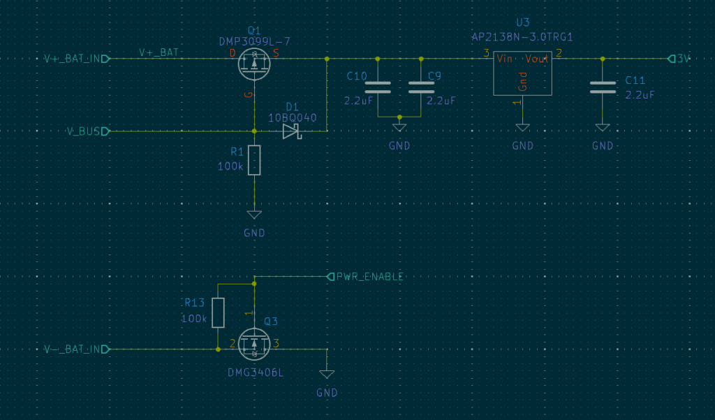
I configured the processor using STs software to make sure I had the pinout right and it would be possible to do what I wanted with this specific package. The PSRAM and temperature sensor were simply power and data interface connections. Nothing high speed and warranting extra attention. The only no so obvious trick was to get the battery and USB power to play nicely together. I want to prioritize the USB power but not let it charge the battery while also not having the device die when USB is removed. A lowside switch with diode to control the gate was the solution to enable seamless power ORing.

Two things I forgot to mention, I decided to power everything from a 3V linear regulator to greatly simplify the power tree and be as efficient as possible when the device is in a low power mode. In my experience linears have lower quiescent currents than switchers. The processor also needs a way to disconnect the battery if it is getting too low. This is between using a battery with full BMS and using a completely unprotected cell. It will at least ensure that the battery is not discharged too deep.
Once everything was connected up in the schematic and it was looking like it was time to layout the design, the feature creep set in. This thing is great and all, but in order to retrieve the data I have to actually go and grab it. What if, I added a small radio that the processor could turn on and blast out its data if it chose to do so. And thus, a header was added for a future expansion with controllable power and UART signals routed to it.
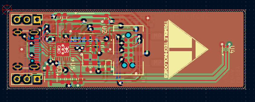
Now the layout could finally begin. Surprisingly, there was no more feature creep and everything was packed in as tight as I could manage. When I was done, I was left with a small stick barely bigger than a flash drive. Though, it is a four layer board.

The only reason it wasn’t shorter was in the vein attempt to improve accuracy and reduce self heating to move the temperature sensor far away from everything else. Now, did I remove all the copper connecting the two? Absolutely not.
Upon assembling the board, it’s quite satisfying how compact but usable it is. So far the base line software is working but nothing low power has been implemented. That will have to wait for a followup article.
