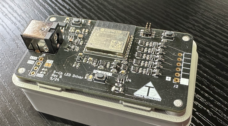
I love LED’s. I love making them light up with different colors and patterns but I’ve never been happy with off the shelf controller offerings. They always seem to have a cloud based hook and be overly complicated to set up and lack even basic features.
So why not make my own?
At its very core it’s simple. Either vary the current through a LED or pulse fast enough the the persistence of vision effect does the dimming for you. So that’s what I did. But with it being so simple I had to make it more complicated. Why not have a bit of scope creep throughout the project.
First I set out to make a three channel driver. Red, green, and blue should be plenty. But what if I wanted a nice white? Better make it a five channel so we can get the color temperature just right. OK, that’s easy enough. Design one driver and use the power of KiCad’s hierarchical sheets to make as many drivers as I want.
Now, from the beginning I knew that the brains of the operation would be an ESP32. But those modules are large, and I have a habit of making the absolute smallest board I possibly can for some reason. Years of MEs complaining that my tiny enclose on their massive machine was too big I suppose. The C3 variant was a bit smaller and had plenty of available pins without feeling like half the chip went to waste.
Right, so I have the brains, I have the drivers but what is going to power the brains? The drivers ride the input voltage but I don’t want to limit myself to just 5V strips. So I took the power supply design from a much older version of this board and dropped it in. No need to redo what is already working. Also carried over a simple header for either an ultrasonic or PIR sensor.
Finally, the stretch goal. I want to have an over current latch off circuit. Just in case the something happens on the output it might just not start a fire. I started with trying to make it as cheap as possible but when that wasn’t working as well as I liked I splurged and spent an extra ten cents on a do nearly everything chip and called it a day. I know, I’m locked in with TI and their chip now but its not like I’m going to be making tens of thousands of these. Unless someone wants to buy them…

Software
It’s just typing after all.
Wanting to integrate this into Home Assistant it was only natural to use ESPHome to do so. A simple yaml file and command line wizard latter and I had an up and running RGBWW light connected. Nothing really much more to say about the software. ESPHome has just been that solid for me.
Conclusion
I ended up with a relatively small, inexpensive, easy to build, easy to load RGBWW driver. I say easy to build because I am very comfortable and proficient at single side reflow soldering. Could it be built with just a soldering iron? Yes, but a lot more work. The only hand soldering required are the connectors, and that was on purpose for mechanical strength. The output connector is probably the one part I’m not completely happy with. I don’t know what I would change it to, but I just want something different.
Overall, very straight forward design, build, and deployment of the project.

