Design Goals:
- Drive a modest length RGBWW LED strip.
- Work with 5-24V strips with no configuration.
- Integrate easily with home assistant.
- Over-current latch
- Ultrasonic/PIR input header
LED Driver
For the driver, a standard low side switch will be sufficient and practically required for driving a strip of LEDs. All of the strips I have and all the strips I came across are common anode.

This means the device will supply voltage to the entire string and switch to ground the color to turn on.
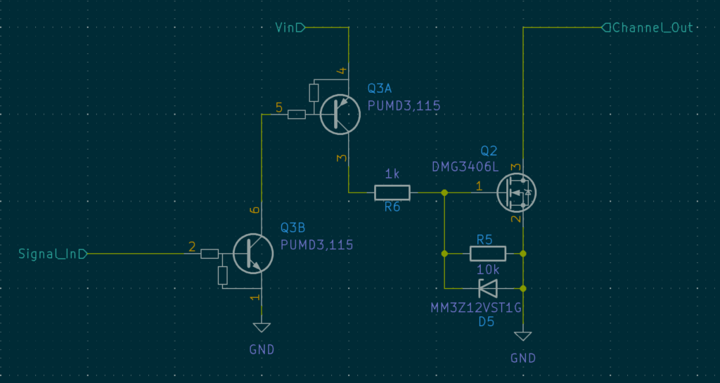
For how much current each switch should be able to handle, I estimated a worst case of two meters of 60 LEDs per meter at max brightness of 20mA comes out to 2.4A. Finding a FET that can handle that much current is not difficult and even come in very small packages. The FET I’ve come to using for situations like this is the DMG3406L. It’s a 30V 3.6A device in a SOT23 package. Nice, small, and very respectable current capacity. The 30V is also a nice margin for the requirement of 24V strips. Since LEDs are more capacitive than inductive I don’t foresee a large spike when switching the string off. The FETs get a small circuit to boost the voltage from the logic level control signal to fully saturate them and protect the gate when using a 24V strip.

Controller
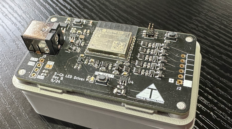
Integrating nicely into home assistant and being able to put these drivers anywhere means wireless control. More specifically WiFi control. This is where the ESP32 comes in. With ESPHome it couldn’t be simpler to integrate and control the LEDs. I chose the ESP32-C3 for its smaller footprint and integrated USB controller, though I wound up not using the USB interface, opting instead for the standard UART bootloader. The ESP32 is in charge of commanding the five driver channels, reading the ultrasonic or PIR input, and monitoring the state of the over current detection and latch circuitry. In the end, it was an almost perfect utilization or pins for this package.
Power supply
With the requirement of 5 to 24V input, and the controller needing 3.3V, I opted for a buck to 5V with a linear to 3.3V. The ultrasonic sensors I have used in the past work much better if they are powered with 5V, or at least something higher than 3.3V. The buck to 5V makes it very efficient to operate from a 12 or 24V supply and the linear makes a cleaner 3.3V rail for the controller and over-current detection circuitry.
Over-current
I wanted a way for the device to protect itself and my house in the event something downstream went wrong. I also did not want to rely on the processor to do this. So a simple high side shunt with op-amp and comparator will detect the over-current. A RC circuit and transistor latch will filter and hold the state of the latch while a pass transistor will disable the supply voltage to all driver gates.
Layout
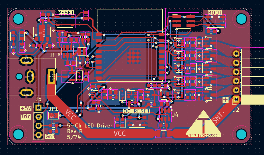
For simple designs like this I like to aim for a credit card sized PCB if at all possible. Single sided to aid in the assembly too since I’ll be assembling it by hand with a hot plate and soldering iron. Two layer because it’s the quickest and cheapest to get manufactured and there’s no need in burying and shielding traces.

The board came in about 25% smaller than a credit card, single sided, and two layers. In my casual testing, the FETs do not even approach becoming warm and the over-current works how I designed it to. The WiFi connection is very reliable with good signal strength, so the placement of the ESP module is satisfactory.
Lessons Learned
While I would like the over-current circuit to use more generic parts, it really isn’t necessary and I get better performance using a dedicated high side shunt op-amp. The boot and reset buttons are not needed because both are on the ESP-Prog board used to upload the firmware the first time. The connector to the LED strip still leaves something to be desired. I haven’t decided if i want to leave it as a pin to pin connector or solder on a flying lead to latching connector.
